

Geometric stress concentration for a shaft with a transverse hole in bending
Geometric stress concentration factor on the surface of a shaft with a transverse (drilled) hole loaded in bending, from a log10 curve fit in the hole/shaft diameter ratio d/D.
Geometric stress concentration, Kₜ (at surface)2.03
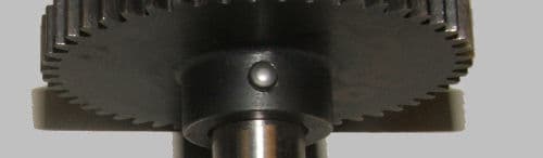
No dedicated diagram exists in the legacy archive for e1_2b.htm — reuses the transverse-hole shaft photo from stress-conc-transverse-hole-torsion (e1_2a.htm), since the two calculators cover the identical physical part (a shaft with a transverse hole) under different loading, not a different geometry.
Method & references
- Kt on the surface of the shaft at the hole, for a shaft with a transverse hole in bending.
- Page's <title>/header text is a copy-paste of the torsion calculator (e1_2a.htm); the visible page heading and this distinct formula confirm it is the bending case.
The computation is a literal port of the original client-side JavaScript from /calculators/e1_2b.htm. Results are verified equal to the original by an automated golden-master test. No formula has been re-derived or “improved”.