
Pinned joint (shaft with a cylindrical transverse pin)
Shear force, shear stress, bearing pressure and torsional stress for a shaft-and-hub joint secured by a cylindrical transverse pin, from shaft/pin diameter, hub thickness and applied torque.
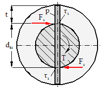
Shear force, Fₛ = T/d_as1000 N
Shear stress in the pin, τ = Fₛ/(π/4·d²)318.31 MPa
Bearing pressure, p = T/((d_as+t)·d·t)66.67 MPa
Torsional stress, τ = T/(π/16·d_as³(1−0.9d/d_as))62.11 MPa
Factor, 1 − 0.9d/d_as0.82
The shear-stress formula uses the legacy literal 3.1416 for π, while the torsion-stress formula uses Math.PI — this inconsistency exists in the original source and is preserved rather than corrected.
Method & references
- Pin diameter typically chosen from the series 1.5, 2, 2.5, 3, 4, 5, 6, 8, 10, 12, 16... mm.
- Reference material: unhardened cylindrical pin, free-cutting steel 95MnPb28 (1.0718), Rm=510 MPa; allowable shear stress 0.9·Rm, allowable bearing pressure Rm/3.
The computation is a literal port of the original client-side JavaScript from /calculators/pinnedjoint.htm. Results are verified equal to the original by an automated golden-master test. No formula has been re-derived or “improved”.