

Hydrostatic collar bearing, slot feed through orifices — fixed reference geometry
Reference-geometry calculator (40mm outer diameter — fixed, matching the original) for a hydrostatic thrust collar bearing fed via a circumferential groove supplied by discrete orifices. Vary groove/inner diameter, film thickness, pressures and fluid properties.
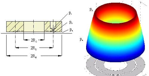
The legacy "please login" demo lock froze the outer diameter D0 to this exact value. Per docs/phase6/OWNER-DECISIONS-BACKLOG.md K4, this fixed geometry is kept exactly as in the original and only the inputs that were already free under the lock are exposed. Generalizing it is a deliberate future decision for Anton, not made here.
Method & references
- Hydrostatic thrust collar bearing fed via a circumferential groove supplied through discrete orifices.
- Shallow-groove/partitioned-groove self-aligning variants require finite element analysis, not covered here.
- FIXED GEOMETRY: outer diameter 40 mm — the original demo lock froze this value.
The computation is a literal port of the original client-side JavaScript from /engineering-abc/calculators/c11_5b.htm. Results are verified equal to the original by an automated golden-master test. No formula has been re-derived or “improved”.